Audio 101 - from Passive to Active
Quick review: a passive EQ uses resistors, capacitors and inductors to change the frequency response of a signal—a filter. However, doing this causes an overall loss of gain, so after that loss caused by the passive filter, there’s an amplifier to bring things back up in level.
What would be an Active EQ? Well, it would be a circuit that doesn’t require the boost of gain after the filter, and instead there's some sort of amplification built into the filter.
First, we need to know what an amplifier is.
An amplifier takes a small signal and makes it bigger. There’s a bunch of cars on the highway. You’re driving on another road. When you speed up or slow down or wiggle your car, ALL the cars on the highway do the same thing as your car. My one car isn’t powering the other cars, but it is controlling the other cars—modulating them. If I “connect” my car to a larger highway I can then control more cars.
How does my car control the other cars on the highway? The road my car is on changes the properties of the highway the other cars are on. If I drive fast, my road makes the highway faster, if I go right, my road bends right and makes the highway bend right.
Let’s call the road my car is on the Control Road. And let’s call the highway The Power Road. Control Road modulates and changes the Power Road.
If I route the car through an obstacle course and keep changing the way the car is facing and turning, speeding up and slowing down, etc, and I put that car on the Control Road, the cars on the Power Road will do the same things my car is doing.
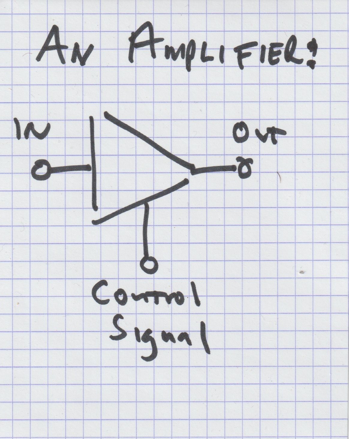
That obstacle course is a filter. If I run a signal through a filter and change it, then put that on the Control Road, then the Power Road behaves in accordance with the physics of the filter.
The roads are paths for cars to follow. The cars are signals. So now we have a Signal coming out of the filter and going into the control, which varies the power.
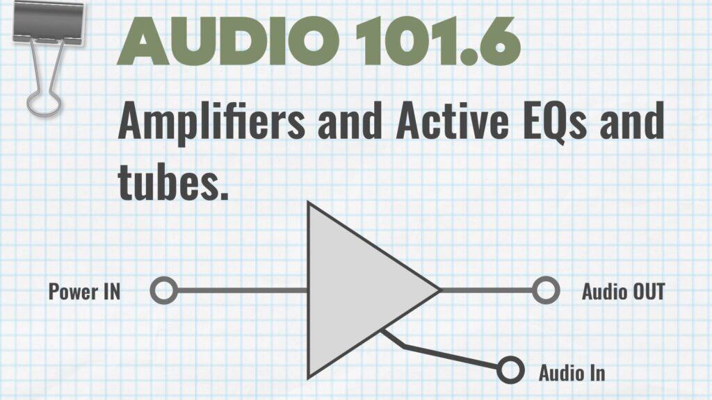
So, the basic construction of an Amplifier is that there’s going to be a path that we can run a lot of cars down—energy. There’s got to be a way to get on that path—we’ll call it the input, and a way to get off of it—we’ll call that the output. And there’s a place to stick a control signal in.
The control signal modulates the output of the amplifier. The control signal doesn’t necessarily directly interact with the power, or the output; what it does is change the properties of the amplifier, which varies the output. Does that make sense to you?
All amplifiers are going to work this way: a smaller signal controls a larger one. What will be different about amplifiers is the technology used to get a bunch of power in a situation where it can be varied (modulated) by a control signal.
In audio, the two technologies most used are Vacuum Tubes and Transistors. They both do the same thing in terms of the end result, but they go about doing it a bit differently.
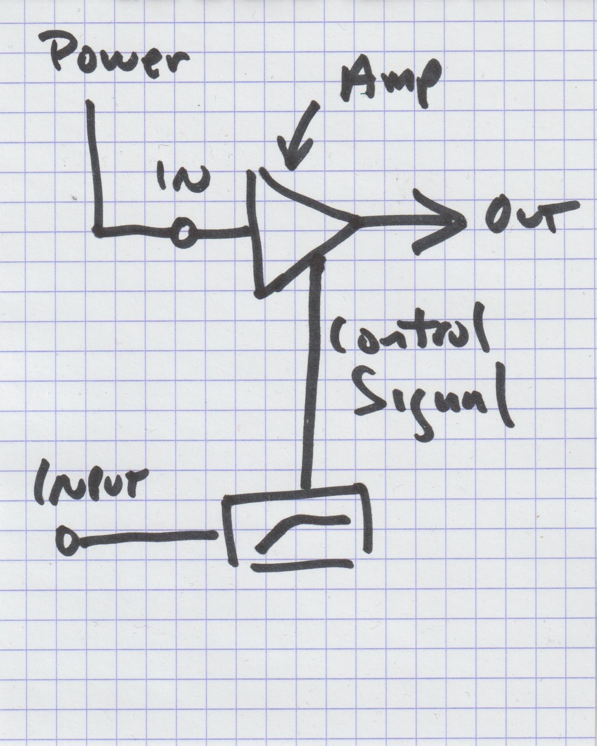
Vacuum Tubes
These are really easy to understand. Inside a tube is a Cathode and a Plate. These aren’t physically touching each other, but what happens is electrons form on the cathode and then jump across to the plate, forming an electric field and a magnetic field. Call it an EM field. In between the cathode and the plate, we stick something called a Grid. The grid interferes with the electric field. The control signal feeds to the grid; the grid interferes with the electric field such that that electric field now “looks” like the control signal, only it’s a lot more powerful.
How does the grid interfere?
Remember, when we have a current, we generate an electric field—wires transmit using an electric field. A grid is basically a bunch of wires, and when we put signal through it, we get an EM field. The EM fields passing from the cathode to the plate interacts with the EM fields around the grid. Depending on how things interact, the energy flowing from the cathode to the plate varies.
To get back to cars, imagine the grid is a network of stoplights and cops, all dictating the flow of traffic.
Tubes, however, don't really work well in active EQ situations. They're heavy, hot, unreliable, and require a lot of calibrating and tweaking, as well as being noisy. But understanding how tubes work will make understanding how transistors work easier when we get to that next week.
Plug-in Errata
Our Amplified Instrument Processor, the AIP, has a four-band parametric EQ in it. It's based on a Siemens tube equalizer from the 1950s, the RZ062.
Like virtually all tube equalizers, the RZ062 was passive, using inductors and capacitors to create filters and then boosting their outputs back up, similar to how a Pultec works. But the EQ on the AIP is fully parametric. What's going on there?
Dan figured out the math to make an RZ062, and then he experimented and rewrote the equations to make a digital version of what would be incredibly difficult to do: make a continuously adjustable parametric EQ out of capacitors and inductors. To give you an example of how difficult this would be: a two-band passive equalizer would require a specific inductor and capacitor set for each band. How many different inductor/capacitor sets would be needed to make an EQ sweeping from 20Hz to 20kHz? 19,980? Something insane like that?
The AIP's EQ has the frequency response curves of an RZ062, and the saturation characteristics of it, without requiring four air-conditioned barns each stuffed with thousands of components for each band.
The AIP EQ, by the way, is gorgeous. It has about the sweetest high-end band of any EQ we've worked with.
Quick question, and feel free to write me, would homework help you to better understand this stuff?