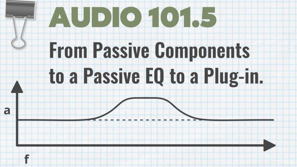
Audio 101 - From Passive Components to a Passive EQ to a Plug-in.
Cut-Off Frequencies
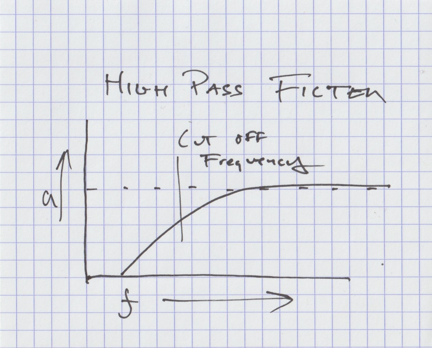
We can make a circuit that lets higher frequencies through using a capacitor. The result is a high-pass shelf—an EQ curve where the low end drops off and the highs stay level.
By adjusting the value of the capacitor and the other elements in the circuit, we can control the frequency where the low end begins to fall away. We call this the cut-off frequency—the point where the shelf starts dipping.
We can also make a circuit that lets lower frequencies through using an inductor. This produces a low-pass shelf, a mirror image of the capacitor version. The lows stay level, and the highs roll off.
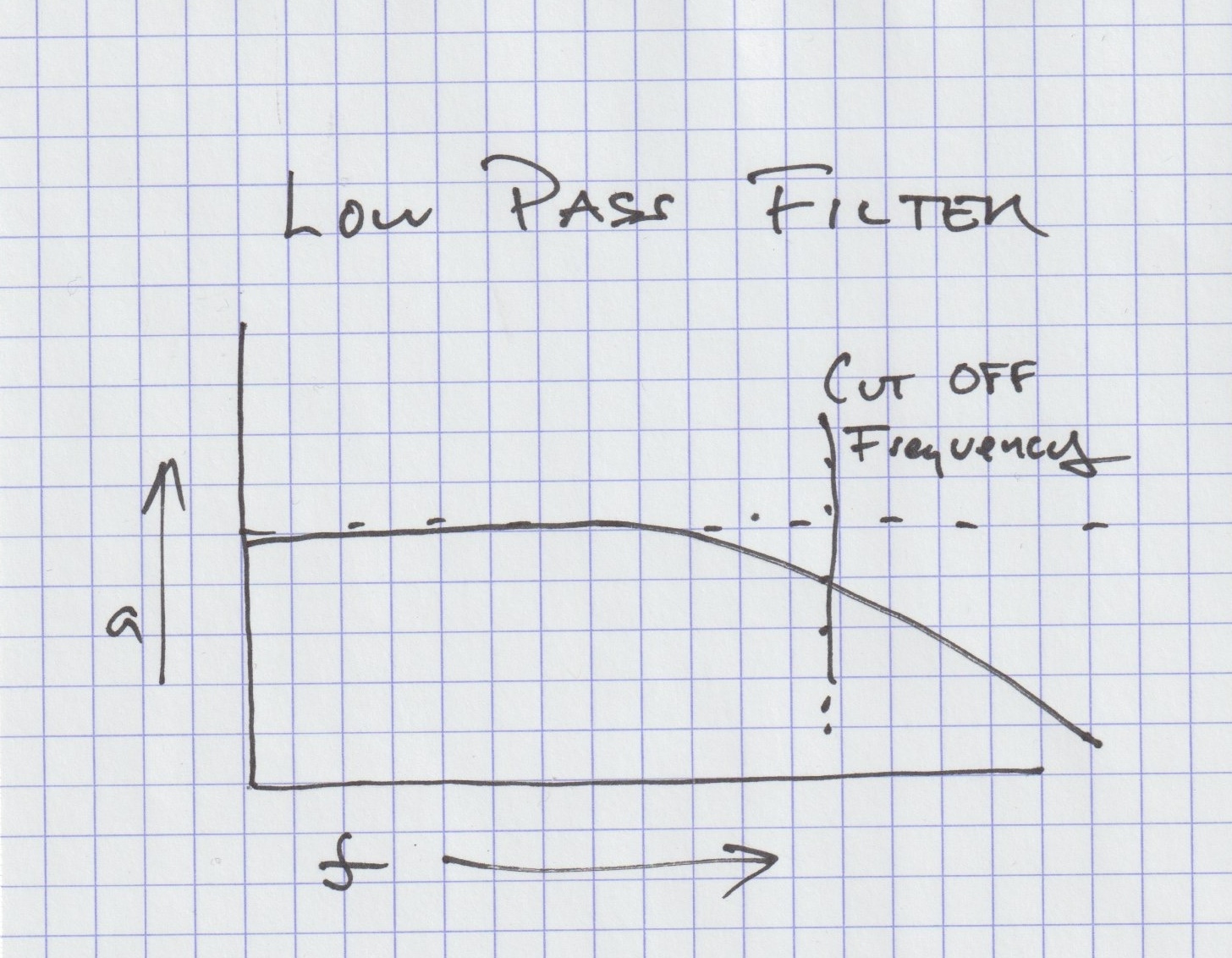
And by adjusting the inductor and the components around it, we control the frequency where the high end begins to fall away. This is also called the cut-off frequency—the point where that upper shelf starts dipping.
If we combine those two circuits together, we get one that shelves away the lows and shelves away the highs, leaving only the frequencies in the middle. That is called a band-pass filter.
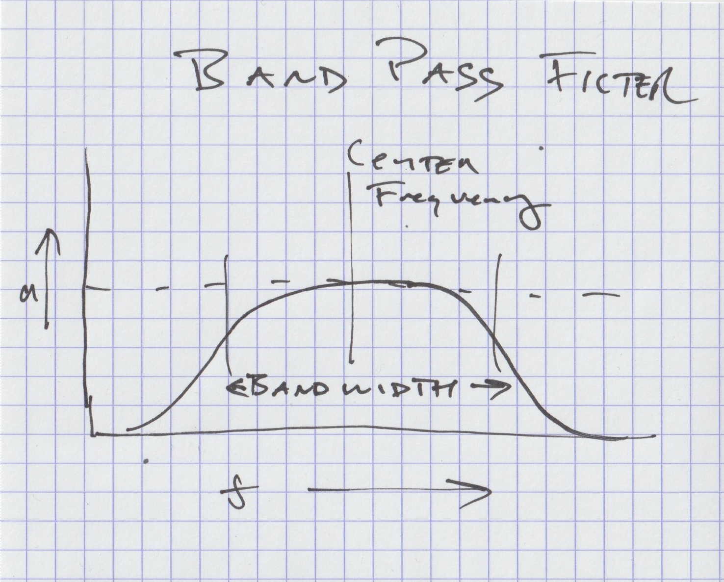
The distance between the high-pass cut-off frequency (where the lows get removed) and the low-pass cut-off frequency (where the highs get removed) is called the bandwidth. The wider the distance between those two cutoffs, the wider the band of frequencies that passes through. The closer they are, the narrower the band.
A band-pass filter doesn’t really have one cutoff frequency — it has two. There’s a cutoff at the low end, where the high-pass section starts allowing frequencies through, and a cutoff at the high end, where the low-pass section starts blocking them.
The frequency right in the middle of those two cutoffs is the center frequency—that’s the one the band-pass filter passes the strongest.
All of these circuits above work by getting rid of frequencies. No matter which one we use, the audio signal feeding in loses power. Using these circuits by themselves, we can cut the bass, cut the highs, or cut both the bass and the highs, leaving only the middle.
Boosting with a Passive EQ
Now… if we want to make the highs louder — like a high-shelf boost — we can’t do it directly with passive parts, because passive circuits can only cut. So what we do instead is:
Step 1: Use a high-pass shelf to cut the bass, leaving the highs less affected.
Step 2: Then amplify everything that comes out of that filter.
The result is that the highs appear boosted, even though all we did was cut the lows first and then re-amplify the entire signal. That’s how passive EQ “boost” works.
To make the lows louder — a low-shelf boost — we do the same thing but at the opposite end of the spectrum:
Step 1: Use a low-pass shelf to cut the highs, leaving the lows less affected.
Step 2: Then amplify everything that comes out of that filter.
To make an area in the midrange louder, we combine the two shelves:
Step 1: Use a high-pass shelf to cut the bass, leaving the highs less affected.
Step 2: Use a low-pass shelf to cut the highs, leaving the lows less affected.
Step 3: Then amplify everything that comes out of that filter.
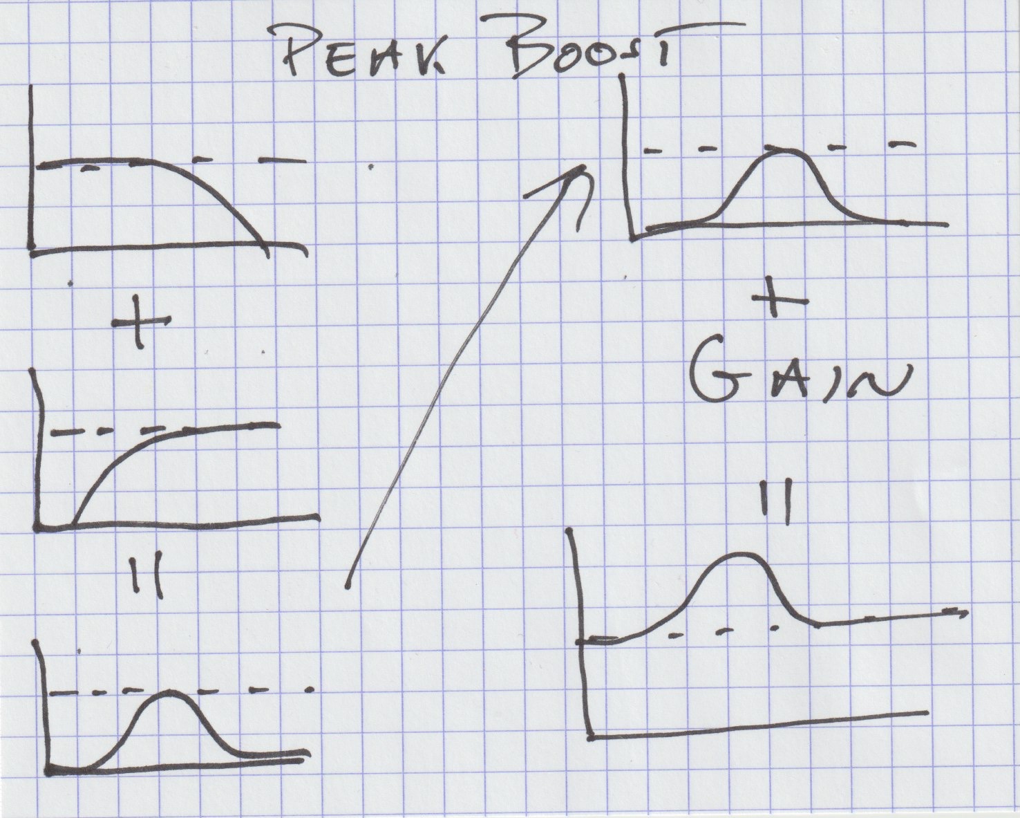
What’s left — the band in the middle — ends up louder after the make-up gain. That’s a passive midrange boost, better known perhaps as a Peak Boost.
We’ve figured out how to make EQ circuits that reduce the power in areas of the frequency spectrum, and we’ve figured out how to make circuits that raise the power in areas of the frequency spectrum.
What if we want to cut some frequencies and boost others at the same time?
Easy: we just combine all of these individual circuits into one larger network.
Everything we want to cut gets its own part of the circuit.
Everything we want to boost gets its own part of the circuit.
In other words, cutting the low end and boosting the low end aren’t two aspects of one function — they’re two completely separate circuits, each designed to shape the signal in its own way. The EQ lets us use them together at the same time.
The reality of these different boosting and cutting circuits is that they aren’t precise opposites of each other. A passive low-shelf cut doesn’t perfectly mirror a passive low-shelf boost. The shapes of the curves depend on the actual circuit design, and they can be very different from one another.
The Pultec Low-End Trick
Most of you know the classic Pultec EQP-1. It’s a passive EQ, built on the principles we’ve been talking about — though in practice, the real circuit is a lot more intricate than our simplified explanations. It can boost and cut at various frequencies, but remember: boosting and cutting live in separate parts of the circuit, so their curves don’t line up like mirror images.
That’s the whole basis for the famous “Pultec Low-End Trick.”

An engineer dials in a low-frequency cut with one knob, and a low-frequency boost with another. Because the cut curve and the boost curve are shaped differently, they don’t just cancel each other out. They overlap and interact. The cut provides one shape, the boost a different shape. The resulting curve is a wide shelf boost with a dip above it. How this sounds is a huge amount of lows with a chunk taken out of the low mids — this is a very common sort of EQ move to make.
The Pultec has the sound it has not only because of the shapes of its EQ curves, but because there are amplifiers in there providing makeup gain. But it’s even crazier than that.
When we think about a circuit — whether it’s the circuit in a Pultec, a compressor, or an entire console — we tend to picture it like a flowchart:
Input → low-shelf section → high-shelf section → makeup gain amplifier → output
For a compressor we might picture:
Input → detector circuit → gain-reduction circuit → makeup gain amplifier.
This is a convenient way for us to understand signal flow. It’s how we visualize what goes where and in what order.
But that isn’t what’s actually happening physically.
Electricity in a circuit moves at just under the speed of light. Which means that, for all practical purposes, the signal is everywhere in the circuit at once. It’s arriving at the input, being cut, boosted, amplified, filtered, and showing up at the output simultaneously.
And because of this, every part of the circuit affects every other part of the circuit — all the time.
The boost affects the cut affects the makeup gain amplifier affects the input affects the output affects the boost ad infinitum.
Everything pushes and pulls on everything else, all at once.
And because impedance changes with frequency, this interaction is slightly different for every frequency that’s in the circuit.
The overall tone, personality or “sound” of a piece of gear is the total result of all of these interactions happening simultaneously. That’s why no two EQs sound the same, even if they technically perform the same EQ moves on paper, and why we like how some EQs sound for certain tasks in the studio, why one might sound warm, another might sound clinical.
People speak of analog gear as sounding “alive.” This is why. Because the entire thing is reacting to itself at just below the speed of light. If you add microphones in, or an amplifier and a speaker, they become part of the whole, interconnected at almost light speed, the whole thing “breathing."
But What About Plug-ins
Let’s take this into the digital realm. Let’s make an EQ plugin. There are two ways to do this. Simple way first:
We can have chunks of program — a little routine that does a shelving EQ, another that does a peaking boost, another that lowers gain, another that adds distortion, etc. Think of these as Lego blocks.
We build these Lego blocks into a structure that does equalization, compression, saturation, whatever we want. We can swap in different blocks with different characteristics, and we can even fine-tune those individual blocks. We can absolutely get something that sounds very good, and it might even get close to the sound of a particular analog unit.
But what it can’t do is interact with itself the way a real analog circuit does.
In our Lego-style plugin, audio flows through one block, then the next, then the next. The output of Block A feeds Block B, but Block B doesn’t naturally “push back” or interact with Block A. The output can’t affect the EQ curve, the distortion, or the dynamics unless we explicitly program that to happen.
In an analog piece of gear, that kind of interaction happens as a consequence of the circuit’s existence. Everything is talking to everything else all the time, because it’s all one continuous electrical system, not a row of separated Lego blocks.
Now, there’s the complex way to make a plugin.
Early on, we looked at some formulas for Current, Voltage, Resistance, and Impedance. We didn’t get heavily into the math of things, but every section of a circuit can be described by a math equation. Capacitors, inductors, resistors, amplifiers—they’re all describable by an equation. In fact, the entire piece of equipment is a bunch of equations which become part of a giant equation that is the math of the circuit and describes what the circuit is doing at any given moment.
To digitally model a piece of analog equipment, one has to figure out the math of all the different sections of the circuit and then combine them into one massive circuit/equation and then have the computer solve all those equations at the same time. If you do it this way, then one section of the equation can affect another section of the equation. Which means the digital circuit is responding to itself in the way an analog circuit responds to itself.
How often does the equation have to be solved? Well, at a sample rate of 48kHz, it has to be solved at 48,000 times a second. How accurate is the solution to the equation? Whatever the bit rate is — 24 bit, 32 bit float, whatever it might be.
Obviously, doing things this way, which is called Component Level Modeling, typically requires more out of the computer system than Lego style.
Which one, Lego Style or Component Level Modeling, sounds more alive and analog? Which one requires more work?
Here’s a surprise that shouldn’t be a surprise: Korneff Audio’s plugins are Component Level Modeled. Yes, Dan sits there, behind a computer, and figures out the math. These days he has a standing desk, so he also stands there and figures out the math.
Once we figure out the math, we get our hands on the actual hardware thing and compare it to the math. In the case of our Shure Level-Loc, first we did the math, then flew to Chicago to work with Shure and Tchad Blake to fine tune the math so it sounded even more like the actual hardware. In fact, we mathematically modeled three different hardware units, all of which are available on our Shure Level-Loc plugin.
Not every plug-in developer does the math. We do.
We’re actually working on a bunch of mathy stuff right now, and you’ll all get to see it as a new plug-in soon.